Workshop Part 2

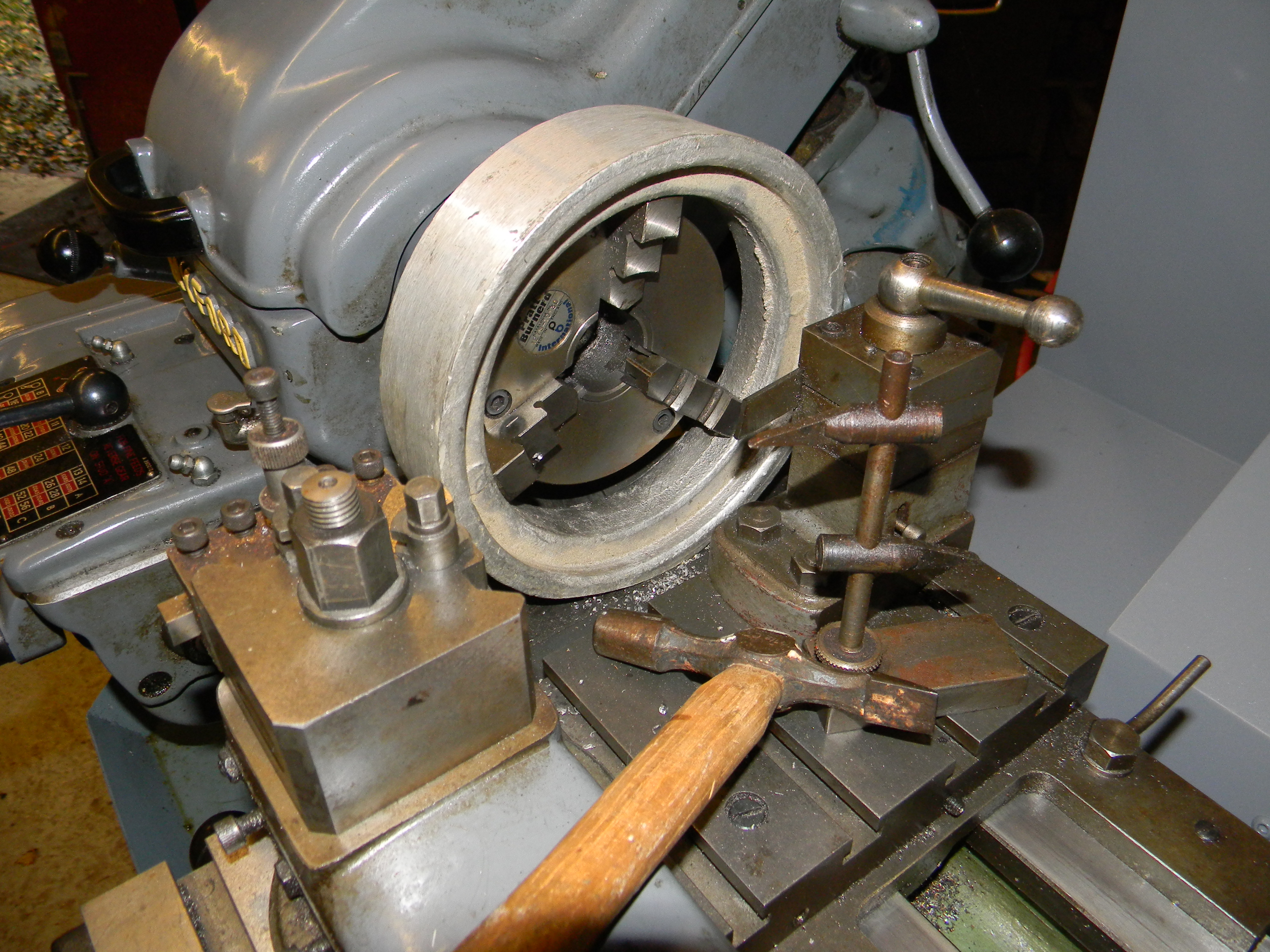
First off – a warning. Myford lathe chucks screw onto the mandrel, therefore DO NOT USE IN REVERSE, as I said I did last time.


2015-11-13 10.10.17
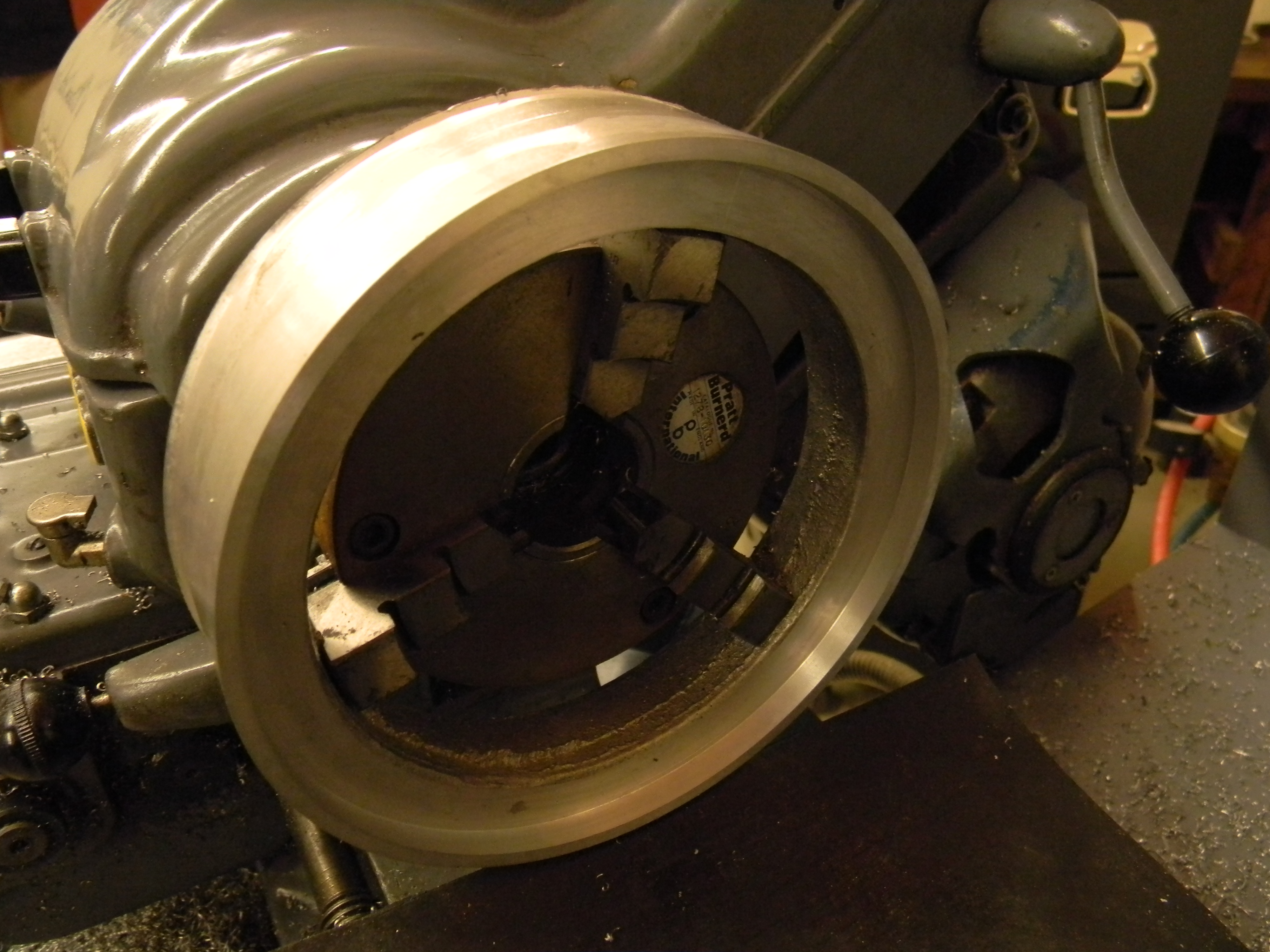
Now, here is the first photo. Why a boring bar in a vice? Well, the finish on the outside of the wheel was not the best (somewhere near the worst) so I brought along my biggest bar. Easy, put into a tool holder and carry on. Not so lucky. Had to take quite a few file strokes to get it down to a size to fit. At least I took it off the two sides adjacent to the holding slit!

2015-11-13 10.59.38
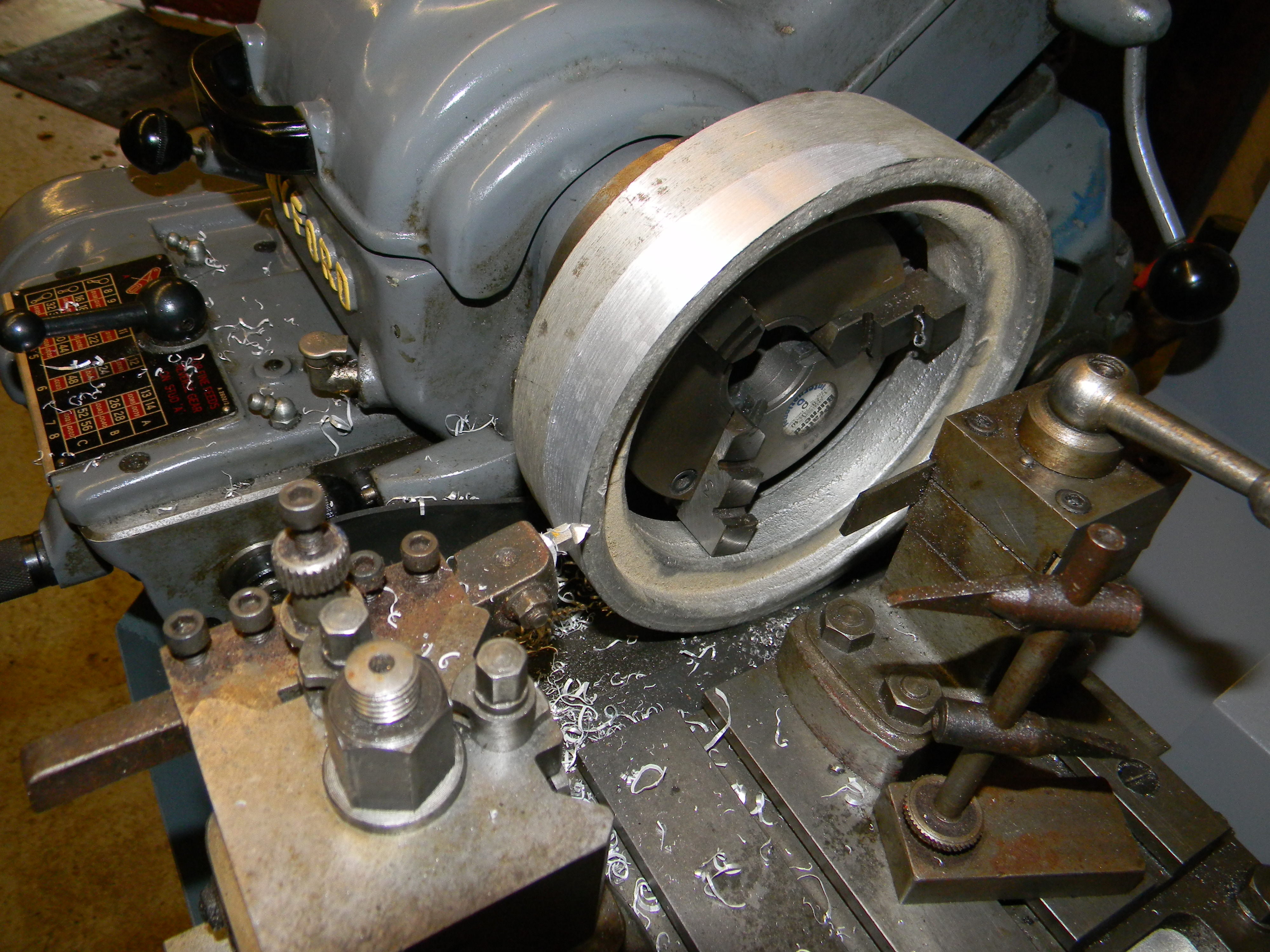
Outside finished to size and an insert tool being used to bring the web clean and to then bring the rim to finished thickness. The depth of the web to the edge can then be determined and taken down to the required size.

2015-11-13 11.29.49
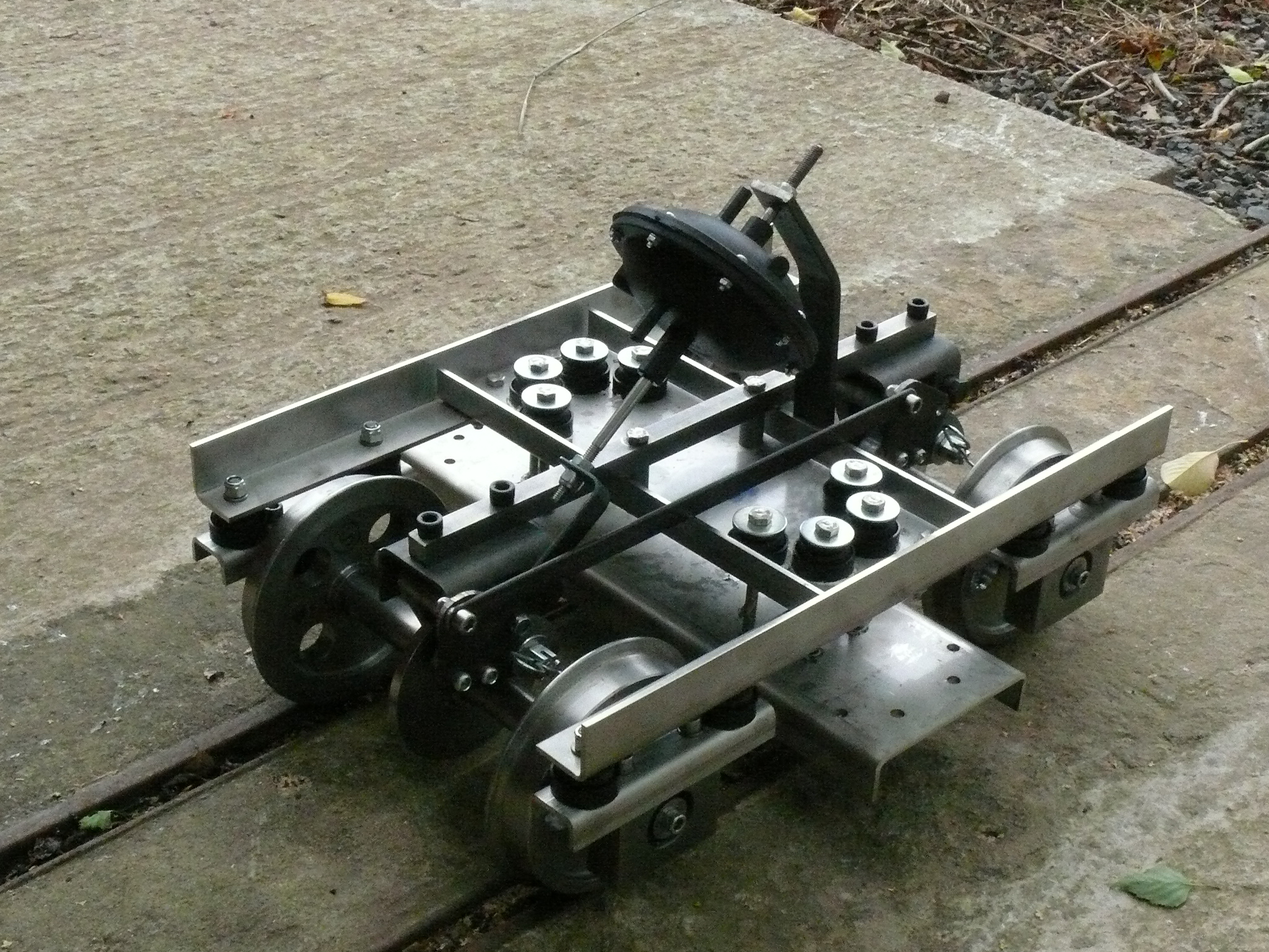
That’s it. One side of one wheel done. Will update again when all the other sides/wheels are finished and I can make a tool to take out the middle of the web.

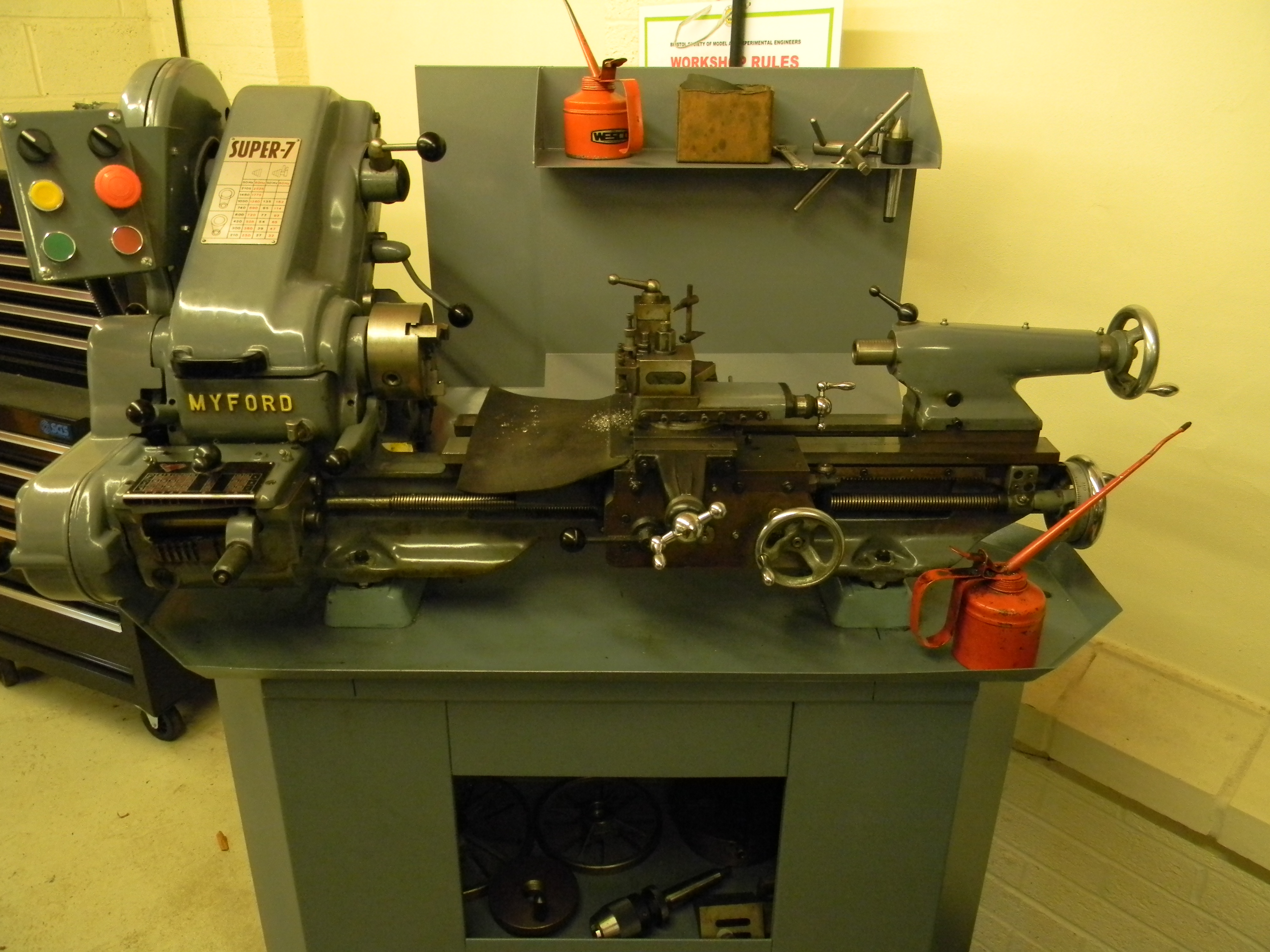
Don’t forget that the workshop is open to all our members. You can use it for any of your larger requirements. A Bridgeport mill has been acquired and will be installed shortly to fit alongside our larger lathe, for those of you who already have a Myford. Please note, I have cleaned up, good workshop practice to leave it ready for the next operator.

Just ask.

Alan Hooper

Using the Workshop

Evening all

I thought it might be of interest to show how the Workshop is operating. Today, on a particularly wet morning during the maintenance Friday morning, I have brought to the site the rear wheel castings for the 1″ Minnie traction engine. Some of you will remember that I spent most of the last exhibition machining some of the castings. Well I thought that I should perhaps get the large rear wheels to the same ‘roughed out’ standard. Now I know most of you will have the necessary machinery to do this at home, but I don’t, having only a 2.1/2″ lathe.

2015-11-06 10.05.21This is our machine, a ML7, refitted back in the workshop. If you come up to the site, please be aware that there must be two people in the workshop. Just basic safety as it is not like being at home. You must also remember to bring any tooling required although for this machine there is a fairly extensive selection available. Measuring tools are also needed.

2015-11-06 10.06.27This photo shows what I brought up with me.

2015-11-06 10.10.41Now, not wanting to teach all you engineers how to suck eggs, I’ll just run through what the procedure was I used. Tool inserted into post. Casting mounted via the inside jaws. The hammer is there to knock the casting into a reasonably circular orbit and the chuck tightened.

2015-11-06 10.33.24Now, I only intend to rough machine these castings rather than do all the cutting in a single stage. Time consuming maybe, but a lot safer for those of self taught machinist! Unfortunately the topslide would not let me reduce the diameter across the complete face so another set was required.

2015-11-06 11.23.53This picture shows a boring bar mounted upside down and with the lathe running in reverse. Much to small a boring bar but nothing else was found on site and you guessed it, I didn’t bring one with me. It did it, though there is a lot of chatter marks.

I did have two more photos, but the site seems not to let me add them to this post. No doubt I’m doing something wrong – again. They where to show that the front face was cleaned back and lastly, because I had to leave early to return the car to ‘her indoors’, I did clean up the lathe. I do not want to be on the wrong side of the Workshop Manager!

I will continue this should anyone be interested.

Alan Hooper. Secretary


Request for information


I’ve just managed to obtain a set of castings for a drill press like the one pictured here:
https://www.bristolmodelengineers.co.uk/gallery/tools/to15.htm

I was wondering if the owner of this machine still had any of the
instructions for machining the castings and/or any arts lists for it?

I would be very grateful if you could pass this request to the person
who is best placed to answer my query.

Secretary: Anyone have any knowledge I can pass on please?

Software drawing package for Apple Computer.

Drawing Program for Apple Computer.

Can anyone please recommend a simple drawing package which will run on an Apple computer.    2D and 3D capability required but perhaps this will need 2 separate packages.  I have been using Autosketch for some time but this has to run on a Windows emulator which is a pain.

I am aware that this post is more suitable for a forum but cannot find forums on our present web site.   Assistance would be most welcome.

Bob Lilley

Polly’s Perfect Performance

Took the club’s Polly 6 to Maidstone MES to represent BSMEE at the Polly Owner’s Group Rally on Saturday 26th September. It ran faultlessly all day and gained some very positive comments from a number of other participants, particularly on the paint finish and the general smooth running. Even got a big ‘thumbs up’ from Andy Clarke, owner of the manufacturer, ‘Polly Engineering’. The track is set in the beautiful Mote Park, Maidstone, Kent and is approximately the same length as our track at ACR. We then ran the loco on Sunday 27th for a full day of passenger hauling at Ashton Court. It was in steam continuously from 11.50 am until 17.15 pm. and once again ran faultlessly. For those involved in the build and those currently involved in the maintenance, give yourselves a good old pat on the back!

The hazards of passenger hauling at ACR

This shows my 5″ Ajax smoke box after 4 hours of public running on Sunday 2nd August 2015. I don’t think there was any room left in there for more ash. It’s a miracle she was still running at all – and I was still carrying passengers! (just) Full Smoke Box

I’m not sure which of us was in a worse state – me or the loco!

Dirty Driver

Give us a Brake!

The first Hudson-James Mk III now with brakes fitted

The first Hudson-James Mk III now with brakes fitted (click for a closer view)

New Ground Level Bogies update.

Another milestone has passed, with the Hayes 210M brake callipers and PNP actuator now installed on the first bogie. Note how the David Hudson self-steering layout eliminates the traditional central bolster and pivot, making it possible to fit the disc brakes and the vacuum gear on the bogie centre line. This makes the whole unit self-contained, which would be difficult to achieve with earlier forms of bogie construction.

Ron James and I have finalised the brake linkage after much thought and a few false starts. A number of improvements have been made over the Mk I and Mk II iterations in developing this Mk III production version:

  • Brake Lever Extensions secured with ¼” pop-rivets for improved head clearance.
  • Brake Lever Extensions have an extra tapped hole for the actuator connecting rod ‘big end,’ to improve the geometry and eliminate clashes.
  • Coupling rod is now solid; adjusters were found to be superfluous.
  • Brake adjustment and balancing is now exclusively by means of the castle nuts on the callipers (as designed).
  • Split pins on the castle nuts replaced by R-clips for ease of maintenance.

Experience with our Mk I and Mk II Hudson-James bogies has shown that very little actuator force is required. The design challenge in fact is to minimise wheel locking, particularly when vehicles are lightly loaded; hence the intentionally short lever arm for the ‘big end’ of the actuator con rod. However to ensure good performance when fully loaded, all carriage wheels will be braked, so this gear will be fitted to every new bogie, and eventually retro-fitted to unbraked examples of the previous Marks.

As a further control, we will be standardising the train vacuum after trials, and fitting limiter valves to prevent the standard vacuum being exceeded.

Our next step is to replicate this bogie so that we can install the pair to refurbished carriage no 201.

Gary Locock